Subscribe to Our Social Media For Prompt Post
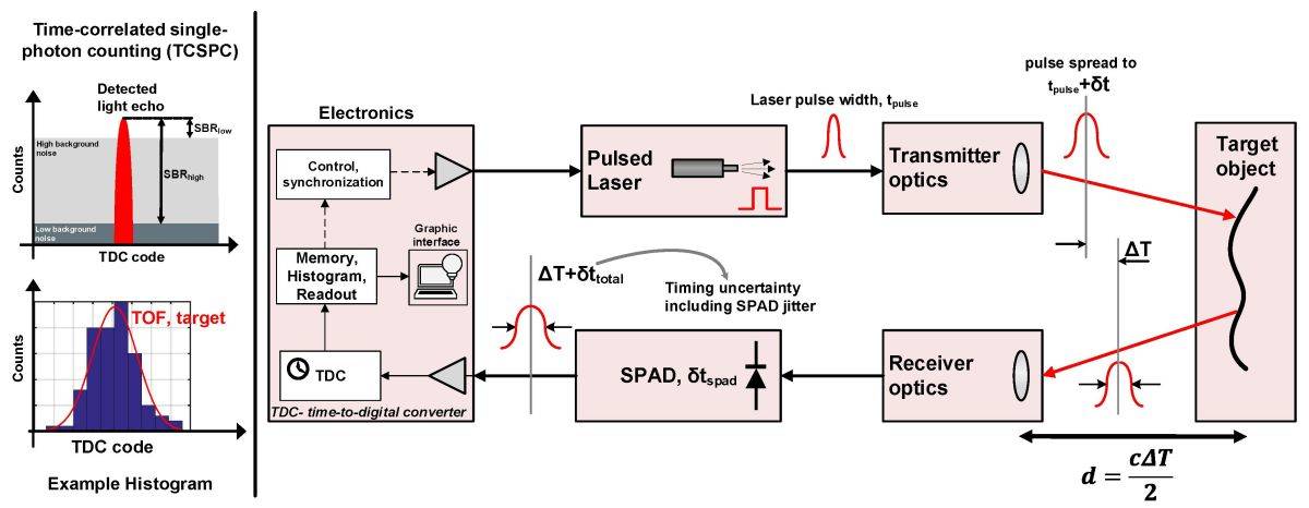
Direct Time-of-Flight (dTOF) technology is an innovative approach to precisely measure the flight time of light, utilizing the Time Correlated Single Photon Counting (TCSPC) method. This technology is integral to a variety of applications, from proximity sensing in consumer electronics to advanced LiDAR systems in automotive applications. At its core, dTOF systems consist of several key components, each playing a crucial role in ensuring accurate distance measurements.
The Core Components of dTOF Systems
Laser Driver and Laser
The laser driver, a pivotal part of the transmitter circuit, generates digital pulse signals to control the laser's emission via MOSFET switching. Lasers, particularly Vertical Cavity Surface Emitting Lasers (VCSELs), are favored for their narrow spectrum, high energy intensity, fast modulation capabilities, and ease of integration. Depending on the application, wavelengths of 850nm or 940nm are selected to balance between solar spectrum absorption peaks and sensor quantum efficiency.
Transmitting and Receiving Optics
On the transmitting side, a simple optical lens or a combination of collimating lenses and Diffractive Optical Elements (DOEs) directs the laser beam across the desired field of view. The receiving optics, aimed at gathering light within the target field of view, benefit from lenses with lower F-numbers and higher relative illumination, alongside narrowband filters to eliminate extraneous light interference.
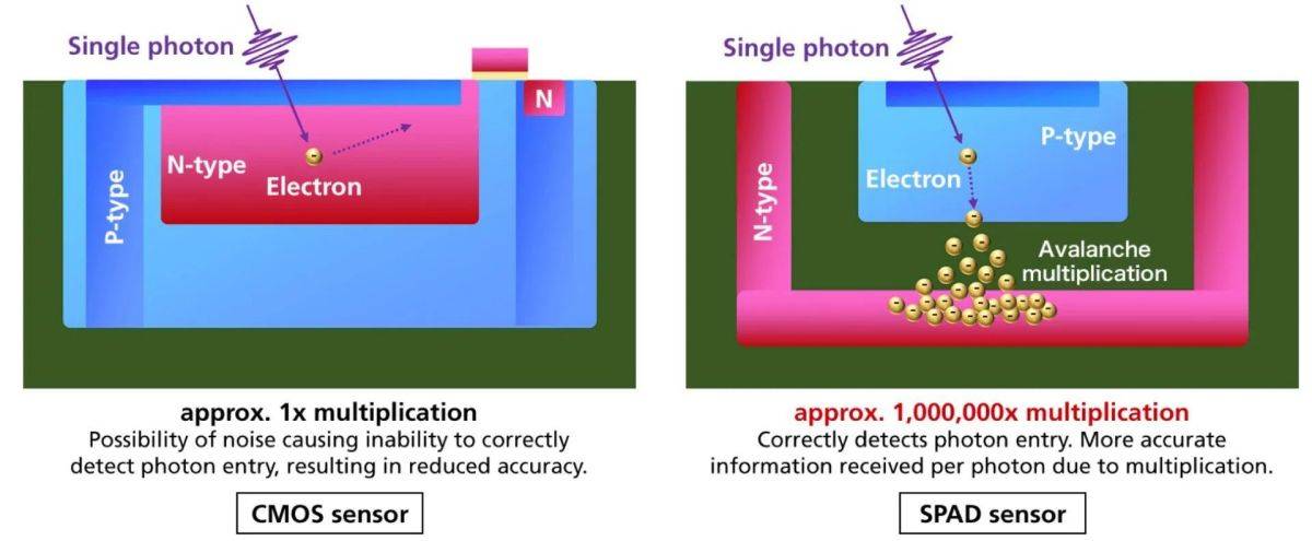
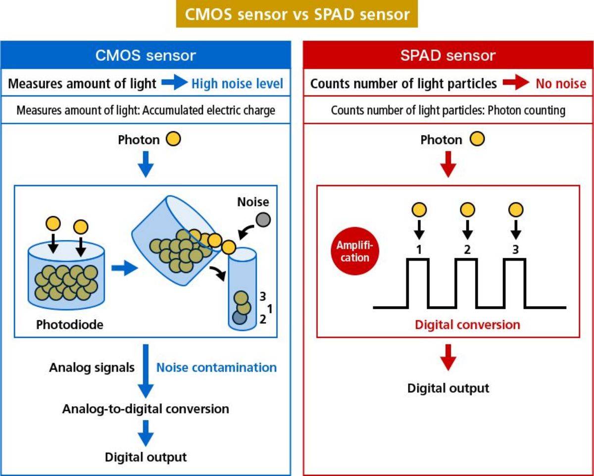
SPAD and SiPM Sensors
Single-photon avalanche diodes (SPAD) and Silicon photomultipliers (SiPM) are the primary sensors in dTOF systems. SPADs are distinguished by their ability to respond to single photons, triggering a strong avalanche current with just one photon, making them ideal for high-precision measurements. However, their larger pixel size compared to traditional CMOS sensors limits the spatial resolution of dTOF systems.
Time-to-Digital Converter (TDC)
The TDC circuit translates analog signals into digital signals represented by time, capturing the precise moment each photon pulse is recorded. This accuracy is crucial for determining the position of the target object based on the histogram of recorded pulses.
Exploring dTOF Performance Parameters
Detection Range and Accuracy
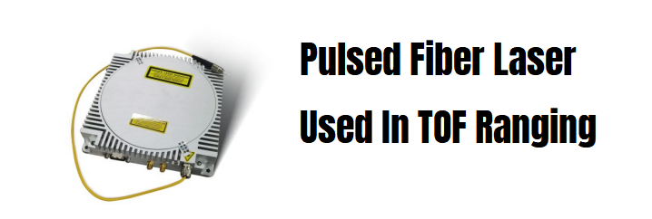
The detection range of a dTOF system theoretically extends as far as its light pulses can travel and be reflected back to the sensor, identified distinctly from noise. For consumer electronics, the focus is often within a 5m range, utilizing VCSELs, while automotive applications may require detection ranges of 100m or more, necessitating different technologies like EELs or fiber lasers.
click here to learn more about the product
Maximum Unambiguous Range
The maximum range without ambiguity depends on the interval between emitted pulses and the modulation frequency of the laser. For example, with a modulation frequency of 1MHz, the unambiguous range can reach up to 150m.
Precision and Error
Precision in dTOF systems is inherently limited by the pulse width of the laser, while errors can arise from various uncertainties in the components, including the laser driver, SPAD sensor response, and TDC circuit accuracy. Strategies like employing a reference SPAD can help mitigate these errors by establishing a baseline for timing and distance.
Noise and Interference Resistance
dTOF systems must contend with background noise, particularly in strong light environments. Techniques such as using multiple SPAD pixels with varying attenuation levels can help manage this challenge. Additionally, dTOF's capability to distinguish between direct and multipath reflections enhances its robustness against interference.
Spatial Resolution and Power Consumption
Advancements in SPAD sensor technology, such as the transition from front-side illumination (FSI) to back-side illumination (BSI) processes, have significantly improved photon absorption rates and sensor efficiency. This progress, combined with the pulsed nature of dTOF systems, results in lower power consumption compared to continuous wave systems like iTOF.
The Future of dTOF Technology
Despite the high technical barriers and costs associated with dTOF technology, its advantages in accuracy, range, and power efficiency make it a promising candidate for future applications in diverse fields. As sensor technology and electronic circuit design continue to evolve, dTOF systems are poised for wider adoption, driving innovations in consumer electronics, automotive safety, and beyond.
- From the web page 02.02 TOF系统 第二章 dTOF系统 - 超光 Faster than light (faster-than-light.net)
- by the author: Chao Guang
Disclaimer:
- We hereby declare that some of the images displayed on our website are collected from the Internet and Wikipedia, with the aim of promoting education and information sharing. We respect the intellectual property rights of all creators. The use of these images is not intended for commercial gain.
- If you believe that any of the content used violates your copyright, please contact us. We are more than willing to take appropriate measures, including removing images or providing proper attribution, to ensure compliance with intellectual property laws and regulations. Our goal is to maintain a platform that is rich in content, fair, and respects the intellectual property rights of others.
- Please contact us at the following email address: sales@lumispot.cn. We commit to taking immediate action upon receiving any notification and guarantee 100% cooperation in resolving any such issues.
Post time: Mar-07-2024


