Subscribe to Our Social Media For Prompt Post
This series aims to provide readers with an in-depth and progressive understanding of the Time of Flight (TOF) system. The content covers a comprehensive overview of TOF systems, including detailed explanations of both indirect TOF (iTOF) and direct TOF (dTOF). These sections delve into system parameters, their advantages and disadvantages, and various algorithms. The article also explores the different components of TOF systems, such as Vertical Cavity Surface Emitting Lasers (VCSELs), transmission and reception lenses, receiving sensors like CIS, APD, SPAD, SiPM, and driver circuits like ASICs.
Introduction to TOF(Time of Flight)
Basic Principles
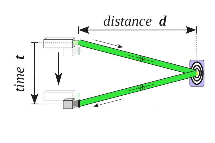
TOF, standing for Time of Flight, is a method used to measure distance by calculating the time it takes for light to travel a certain distance in a medium. This principle is primarily applied in optical TOF scenarios and is relatively straightforward. The process involves a light source emitting a beam of light, with the time of emission recorded. This light then reflects off a target, is captured by a receiver, and the time of reception is noted. The difference in these times, denoted as t, determines the distance (d = speed of light (c) × t / 2).
Types of ToF Sensors
There are two primary types of ToF sensors: optical and electromagnetic. Optical ToF sensors, which are more common, utilize light pulses, typically in the infrared range, for distance measurement. These pulses are emitted from the sensor, reflect off an object, and return to the sensor, where the travel time is measured and used to calculate distance. In contrast, electromagnetic ToF sensors use electromagnetic waves, like radar or lidar, to measure distance. They operate on a similar principle but use a different medium for distance measurement.
Applications of ToF Sensors
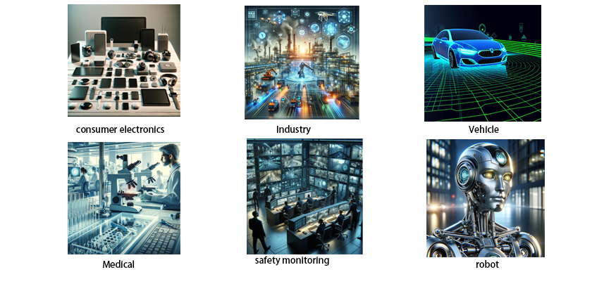
ToF sensors are versatile and have been integrated into various fields:
Robotics: Used for obstacle detection and navigation. For example, robots like Roomba and Boston Dynamics' Atlas employ ToF depth cameras for mapping their surroundings and planning movements.
Security Systems: Common in motion sensors for detecting intruders, triggering alarms, or activating camera systems.
Automotive Industry: Incorporated in driver-assist systems for adaptive cruise control and collision avoidance, becoming increasingly prevalent in new vehicle models.
Medical Field: Employed in non-invasive imaging and diagnostics, such as optical coherence tomography (OCT), producing high-resolution tissue images.
Consumer Electronics: Integrated into smartphones, tablets, and laptops for features like facial recognition, biometric authentication, and gesture recognition.
Drones: Utilized for navigation, collision avoidance, and in addressing privacy and aviation concerns
TOF System Architecture

A typical TOF system consists of several key components to achieve the distance measurement as described:
· Transmitter (Tx): This includes a laser light source, mainly a VCSEL, a driver circuit ASIC to drive the laser, and optical components for beam control such as collimating lenses or diffractive optical elements, and filters.
· Receiver (Rx): This consists of lenses and filters at the receiving end, sensors like CIS, SPAD, or SiPM depending on the TOF system, and an Image Signal Processor (ISP) for processing large amounts of data from the receiver chip.
·Power Management: Managing stable current control for VCSELs and high voltage for SPADs is crucial, requiring robust power management.
· Software Layer: This includes firmware, SDK, OS, and application layer.
The architecture demonstrates how a laser beam, originating from the VCSEL and modified by optical components, travels through space, reflects off an object, and returns to the receiver. The time lapse calculation in this process reveals distance or depth information. However, this architecture does not cover noise paths, such as sunlight-induced noise or multi-path noise from reflections, which are discussed later in the series.
Classification of TOF Systems
TOF systems are primarily categorized by their distance measurement techniques: direct TOF (dTOF) and indirect TOF (iTOF), each with distinct hardware and algorithmic approaches. The series initially outlines their principles before delving into a comparative analysis of their advantages, challenges, and system parameters.
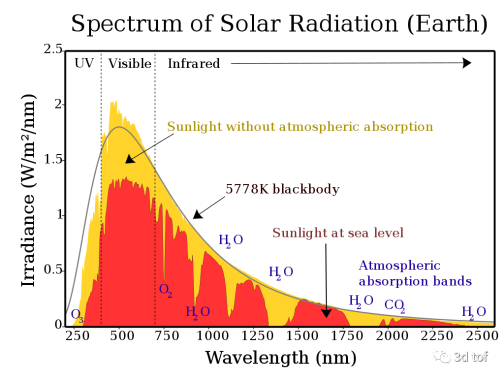
Despite the seemingly simple principle of TOF – emitting a light pulse and detecting its return to calculate distance – the complexity lies in differentiating the returning light from ambient light. This is addressed by emitting sufficiently bright light to achieve a high signal-to-noise ratio and selecting appropriate wavelengths to minimize environmental light interference. Another approach is to encode the emitted light to make it distinguishable upon return, similar to SOS signals with a flashlight.
The series proceeds to compare dTOF and iTOF, discussing their differences, advantages, and challenges in detail, and further categorizes TOF systems based on the complexity of information they provide, ranging from 1D TOF to 3D TOF.
dTOF
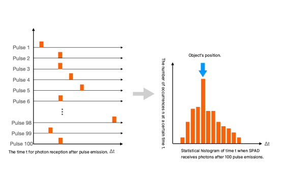
Direct TOF directly measures the photon's flight time. Its key component, the Single Photon Avalanche Diode (SPAD), is sensitive enough to detect single photons. dTOF employs Time Correlated Single Photon Counting (TCSPC) to measure the time of photon arrivals, constructing a histogram to deduce the most likely distance based on the highest frequency of a particular time difference.
iTOF
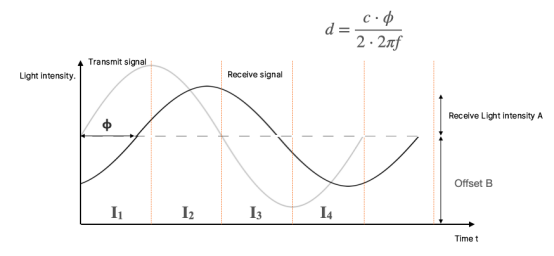
Indirect TOF calculates flight time based on the phase difference between emitted and received waveforms, commonly using continuous wave or pulse modulation signals. iTOF can use standard image sensor architectures, measuring light intensity over time.
iTOF is further subdivided into continuous wave modulation (CW-iTOF) and pulse modulation (Pulsed-iTOF). CW-iTOF measures the phase shift between emitted and received sinusoidal waves, while Pulsed-iTOF calculates phase shift using square wave signals.
Futher Reading:
- Wikipedia. (n.d.). Time of flight. Retrieved from https://en.wikipedia.org/wiki/Time_of_flight
- Sony Semiconductor Solutions Group. (n.d.). ToF (Time of Flight) | Common Technology of Image Sensors. Retrieved from https://www.sony-semicon.com/en/technologies/tof
- Microsoft. (2021, February 4). Intro to Microsoft Time Of Flight (ToF) - Azure Depth Platform. Retrieved from https://devblogs.microsoft.com/azure-depth-platform/intro-to-microsoft-time-of-flight-tof
- ESCATEC. (2023, March 2). Time of Flight (TOF) Sensors: An In-Depth Overview and Applications. Retrieved from https://www.escatec.com/news/time-of-flight-tof-sensors-an-in-depth-overview-and-applications
From the web page https://faster-than-light.net/TOFSystem_C1/
by the author : Chao Guang
Disclaimer:
We hereby declare that some of the images displayed on our website are collected from the Internet and Wikipedia, with the aim of promoting education and information sharing. We respect the intellectual property rights of all creators. The use of these images is not intended for commercial gain.
If you believe that any of the content used violates your copyright, please contact us. We are more than willing to take appropriate measures, including removing images or providing proper attribution, to ensure compliance with intellectual property laws and regulations. Our goal is to maintain a platform that is rich in content, fair, and respects the intellectual property rights of others.
Please contact us at the following email address: sales@lumispot.cn. We commit to taking immediate action upon receiving any notification and guarantee 100% cooperation in resolving any such issues.


Post time: Dec-18-2023


